Pipes
The pipes in the model are couplings between the nodes. Pumps, valves and heat exchangers can be connected to pipes. A pipe is characterised by the name of the connecting nodes, length, internal diameter, roughness, heat transfer coefficient, individual loss, two pressure losses at both ends and the flow in the pipe.
The model assumes that the network is geometrically symmetrical from inlet to return. Various physical units such as diameter, heat transfer coefficient, individual loss, length and roughness can be specified. Pumps and valves can be connected to either the upstream pipe end or the downstream pipe end; see the figure.
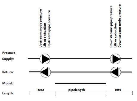
Pipe model defined with lengths and pressures.
A pump can either be described with a pressure increase, ΔP, or by means of a pump characteristic, where the pressure is calculated as a function of the flow in the pipe. The pump velocity can also be calculated when the pressure and flow are described by means of the characteristics. The pump characteristics are indicated by up to 12 points which are described with pressure, flow and power consumption at a specific velocity for the pump. Calculation of ΔP is interpolated from the characteristics.
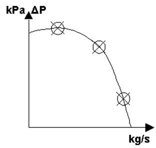
Specification of pump characteristics
A valve is indicated either by an applied pressure loss or by valve characteristics where the pressure loss is calculated as a function of the flow in the pipe at a given valve setting. The characteristics have to be entered as a set of operating points determined by the values of the valve setting and valve coefficient. Up to 10 points can be entered for determination of the characteristics.
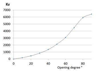
Specification of valve characteristics
A heat exchanger can be connected to a pipe end. Quite simply, the heat exchanger describes an increased or a decreased temperature for the water in the pipe. The power supplied or removed via the heat exchanger is a linear function of the temperature upstream in the pipe.