Location of pumps and valves
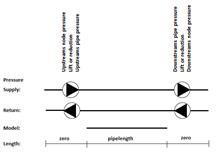 Pump/Valve is a pressure change in the pipe between
the pipe and node 1 or node 2 in the supply pipe, the return pipe or both. Thus
a pipe contains four positions where pressure changes can take place.
Pump/Valve is a pressure change in the pipe between
the pipe and node 1 or node 2 in the supply pipe, the return pipe or both. Thus
a pipe contains four positions where pressure changes can take place.
The pressure change can be fixed or controlled by a reference value. The pressure change can be unknown in just one of these positions. All the other pressure changes in a pipe must be specified in some way. There is one exception. If the a pumping is defined in both supply and return in the same pipe at the same end of the pipe and the head is undefined in both supply and return will the total head required to obtain the pressure/differential pressure given for the set point node be divided between the supply and return pumping according to the quota given for the pumping. Although in many cases it is valid, it is in most cases preferable to locate the pump or valve next to node 1 in the pipe. Further, if a pump lift is defined in both the supply and return of a pipe, pumping may not be placed in adjacent pipes.
Pressure changes can also be described by defining PUMPS and VALVES which are connected to these positions [at the pipe.
When undefined pressure changes are introduced in the pipes, corresponding reference values for pressure must be introduced in the model. This is done by specifying nodes and pressures in these nodes. The stated pressures in these nodes relate to the supply pipe pressure, the return pipe pressure or the difference between the supply and the return pressure, the differential pressure.
Both pump and valve can be supplemented with a characteristic. In the case of the pump, for a given speed, the link between flow, pressure and power requirement. In the case of the valve, the link between opening degree and capacity (Kv value) is stated. These characteristics are presented to the calculation module in the calculation file using the keywords *PUMP and *VALV. These keywords are sent to the calculation file only if the characteristics have been defined.
A pump or valve can be viewed as a framework so as to control pressure changes in the four named positions in the keyword *PIPE, and to control supply, return or differential pressure in the keyword *NODE and ensure that the boundary conditions are sufficient in the model.
The pump location is indicated in the keyword *PUMP: supply+return, supply, return or in node. (The last option is used only for pumps in production plants.) Current speed for location in supply pipe, current speed for location in return pipe followed by the characteristic. Note that the end of the pipe at which the pump is located is indicated in *PIPE.
The location of the valve is indicated in *VALV: supply+return, supply or return. Current opening degree 0 90° from closed position, followed by the characteristic. Note that the same opening degree is applicable to both the supply pipe and the return pipe and that the opening degree is always specified. This means that a characteristic is never indicated for a regulating valve.
A pump and valve are given the name of the pipe in the calculation file. This means that only one characteristic can be given to the respective pipe of either pump and valve.
Therefore, there are a number of valid and invalid combinations that can be entered by the user.
