Example
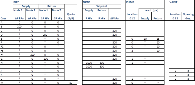
The table below shows a number of combinations of locations of pumps and valves in one and the same pipe with and without reference values. * in a field means that the value is calculated.
(*) Location 0 : located in both supply pipe and return pipe, 1: located in supply pipe, 2: located in return pipe
Reference values in nodes: If a number of reference values have been given in a case, these may relate to the same or different nodes. It is important to note that pressure regulations take precedence over a given reference value.
|
|
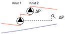
A: |
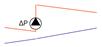
Pipe without pump or valve (pressure increase/pressure reduction). |
|
|
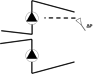
B: |
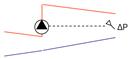
Pump in supply pipe at node 1, lifts 200 kPa. |
|
|
C: |
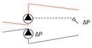
Pump in supply pipe at node 1, lift is calculated so that DP in reference value node is 300 kPa.
|
|
|
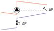
D: |
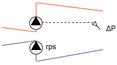
Pump in supply pipe at node 1, lift is calculated so that DP in reference value node is 300 kPa. Pump in return pipe at node 1, lifts 200 kPa |
|
|
E: |
Identical pumps in the supply pipe and the return pipe at node 1 with different speeds. Lift in respective pipe function of speed |
|
|
F: |
Identical pumps in the supply pipe and the return pipe at node 1 with different speeds. Lift in return pipeline function of given speed. Lift in supply pipe is calculated so that DP in reference value node is 300 kPa. The speed is calculated. |
|
|
F2: |
Invalid! Identical pumps in the supply pipe and the return pipe, but located at either end of the pipe! |
|
|
F3: |
Pump at either of the pipe in supply and return. Supply pump lifts so that DP in reference value node is 300 kPa. Speed is NOT calculated! Return pump operates at set speed. |
|
|
F4: |
Pumping at both ends of supply pipe. One pumping set to 200 kPa, the other calculated so that DP in reference value node is 300 kPa. NO PUMP CURVES can be utilised! |
|
|
M: |
Pumpning in the same end of pipe in both supply and return side of pipe. The total lift in supply + return is calculated so that DP in reference value node is 300 kPa. Pump speed is calculated. The total lift is divided between supply and return side according to the Quota given for the pumping. |
|
|
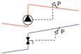
G: |
: Pump in supply pipe at node 1, lift is calculated so that DP in reference value node is 300 kPa. Valve in return pipe throttles 200 kPa |
|
|
H: |
Cannot be resolved! Pump in supply pipe at node 1, lift is calculated so that supply pressure in reference value node is 1000 kPa. Valve in return pipe throttles so that return pressure in reference value node is 500 kPa. Pump speed is calculated! |
|
|
I: |
Can be resolved! Pump in supply pipe at node 1, lift is calculated so that supply pressure in reference value node is 1000 kPa. Valve in return pipe throttles so that return pressure in reference value node is 500 kPa. Pump speed is not calculated! |
|
|
J: |
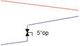
Return throttling at node 1. Valve open 5°, pressure change calculated. |
|
|
K: |
Supply and return throttling at node 1. Valve open 5°, pressure changes calculated. |
|
|
L: |
Can be resolved if pump and valve are located at either end of the pipe! Pump in supply pipe at node 1, lift is calculated so that DP in reference value node is 300 kPa. Valve in return pipe open 5° |