Pump form
The grid form for pumps includes all pumps in the model. In this form, you have a direct overview of how the pumps are set in the model. In the map screen, select the pipe in which the pump is located when you highlight the pump in the grid form. The data which you enter for a pump relates only to the current model. Thus the same pump can be used in several models with different settings!

Some of the columns include drop-down icons which are disabled. These values can be changed instead in the pump's detailed form which you open by double-clicking in the row number column at the far left.
To create a new pump, select Create new in the right-click menu.
 Give
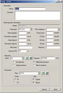
the pump a name or select an existing pump from the list at the top right. If a
pump type is to be entered, select the type from the list. The pump belongs to
the pipe and can relate to a pressure change in the supply pipe, the
return pipe and both the supply pipe and the return pipe. Therefore, you
must enter values for both the supply pipe and the return pipe.
Give
the pump a name or select an existing pump from the list at the top right. If a
pump type is to be entered, select the type from the list. The pump belongs to
the pipe and can relate to a pressure change in the supply pipe, the
return pipe and both the supply pipe and the return pipe. Therefore, you
must enter values for both the supply pipe and the return pipe.
This pump lifts both in the supply and the return pipe, The pump's lift is unknown, and therefore the fields in head supply and head return is empty. The pump is controlled to maintain a 150 kPa differential pressure in node S3 (select type of reference value). Quota S/R is set to 70% which means that 70% of the total lift is taken in the supply pipe and 30% in the return pipe. The pump is located in pipe F4-F5, adjacent to node F4. The icon at the near right of the pipe name field is used to retrieve the pipe which you have highlighted in the map screen, while the icon to the right of this indicates in the map screen the pipe you selected. The icon to the right of the reference value node also retrieves the node which you highlight in the map and the icon to the right of this indicates in the map the node you selected. Max. pump lift and mass flow are items of information sent to the pump control function in Analyse. These values do not restrict the work of the pump in the calculation, but in Analyse they provide information on whether the pump is operating beyond its actual capacity.
If the pump lift is determined, you cannot give a reference value. In this instance, enter no setpoints as the reference value type. If you select a pump type and enter a speed, the pump lift is determined via the characteristic for the pump type. In this case, the field for lift must be empty and the reference value type must be no reference values. See also the section Pressure regulations pumps and valves. Although in many cases it is valid, it is in most cases preferable to locate the pump next to node 1 in the pipe. Further, if a pump lift is defined in both the supply and return of a pipe, pumping may not be placed in adjacent pipes.