Calculation...
The calculation is configured and enabled in the calculation form.
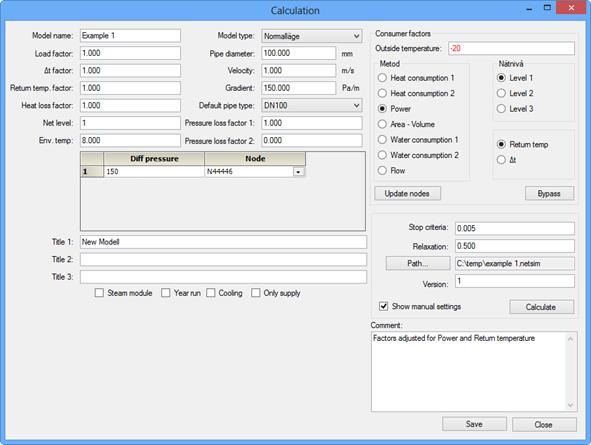
Load
factor:
A given value in node, flow or power is multiplied by the factor in the input
data for the calculation module.
Δt
factor:
A given value in node for cooling is multiplied by the factor in the input data
for the calculation module.
Return temp.
factor: A given value
in node for return temperature is multiplied by the factor in the input data for
the calculation module.
Heat loss factor:
A given value for the pipe types' heat loss factor
(W/m°C) is multiplied by the factor in the input data for the calculation
module.
Network level: Enter 1, 2 or 3 for calculation of all pipes in
the model, distribution
and main pipes or just main pipes.
Ambient temp.: The global ambient temperature against which the heat losses of all pipes are calculated, except for the pipes which have a local ambient temperature specified.
Model type: Planned or normal.
Pipe diam.: (mm) Included in the dimensioning criteria; see below
Velocity: (m/s) Included in the dimensioning criteria; see below
Gradient: (Pa/m) Included in the dimensioning criteria; see below
Default
pipe type: Included in the dimensioning criteria;
see below
Dimensioning criteria: Pipes with an unknown internal diameter are dimensioned as follows: The program makes a selection from pipe types which are approved for use for dimensioning a pipe type which provides the highest stated velocity. If the internal diameter of this selected pipe type exceeds the value given for diameter, a pipe type which gives the highest stated pressure drop gradient is selected instead. If all the pipes in a ring connection are to be dimensioned, the program uses the type specified as the default for one of the pipes in the ring connection. Pipe type ? must not be included in the list.
Pressure loss factor 1: Calibration factor for pressure drop calculation; see below.
Pressure loss factor 2: Calibration factor for pressure drop calculation; see below.
Pressure drop calibration
The calculated pressure drop in the pipe × with factor 1 with the addition of the calculated pressure drop × factor 2 × the internal diameter of the pipe is reported as a pressure drop in a pipe. The defaults are 1 and 0. Common values for factor 1 are in the range 1.05 1.1.
Differential pressure,
node: In the specified node, the pressure difference between the supply pipe
and the return pipe must be the stated value. A differential pressure and node
must be specified for every separate hydraulic network in the model.
Headers 1, 2 and 3: These texts pass out in input data to the calculation module and on to the results files.
Steam system, Annual run: Select whether the model relates to a network for steam and condensate, a district cooling network, if the calculation is to be executed as an annual run, or if only the supply pipe is to be calculated.
Outdoor
temp.: Enter the outdoor temperature
for which factors for power, cooling and return temperature are to be calculated
when updating nodes from customer data. This value is also used when determining
the supply pipe temperature from the production plants.
Method:
Select which value is to be used when updating nodes from customer
data.
Network
level: Select the customer
levels service, distribution or main pipe level to which the customer's data
is to be written when updating nodes from customer data.
Return temp./Δt:
Select which is the values is to be used when updating
nodes from customer data.
Update
nodes: Execute summing of
power/flow, return temp./Δt from customer data to nodes. NB If you change
level, first clean node data (Tools → General updating).
Bypass: Execute summing of bypasses from customer data to
nodes.
Stop criterion: Calculation continues until the difference in pressure between two iterations is less than this value, normally 0.005. If the calculation fails to find a solution before the maximum number of iterations has been exceeded, this is changed to the value which the calculation module has reached. If the value does not exceed 0.09, the result is generally adequate.
Relaxation: The value by which the calculation module has to adjust input data for the next iteration. Normal value 0.5. If the calculation module does not reach a solution, change this value to 0.8 or 0.9.
Enter search path: This field displays the search path and filename for the latest calculation file. Click to change / filename.
Version The value is 1 or 2. This value affects a method used during the simulation. Standard value is 1. Change the value to 2 if the simulation does not converge to the stopping criteria.
Display manual
settings: If this is selected, calculation does not start automatically when
the input data file for the calculation module is complete, but is displayed
only [by the calculation module dialog for selection of a calculation type when
the input data file is complete.
Calculate:
An input data file is generated for the calculation module, and depending on
setting (above), the calculation module is started.
Comment: A plain text field. Use this field to document
valid calibration factors,
etc.
Save: Use this function to save current settings in the form.
Exit: Closes the form without a save function.